

Copyright: ESA/Rosetta/MPS for OSIRIS Team MPS/UPD/LAM/IAA/SSO/INTA/UPM/DASP/IDA/GIUSEPPE CONZO/A.COOPER
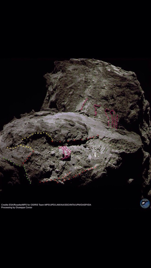
Green- Apis region. Half is in shadow. The two visible sides are the very straight two sides that are at right angles to each other. These are all that’s necessary for this photo because you can see that the side nearest to us has the two red lines leading up to each of its two sharp 90° corners. This 400-metre edge is the straightest 100m scale ridge on the comet and has in effect acted like an anchor beam or like the cross-pole on a deck chair with the fabric sewn round it. The fabric does whatever the pole does and does so across its whole width. The Apis pole pulled the Khonsu fabric across its entire width, pulling Khonsu along its length. Hence Khonsu being long, straight, rectangular, in one plane (but for a few bumps within that plane) and the same width as this Apis edge.
Red- tensile force vectors made visible to us by stretch.
Yellow- a rift. This is where Atum (above Khonsu in this view) proved to be too chunky and brittle to stretch or delaminate so it rifted instead. You can see the lump of Atum to the right of the rift doing its best to keep up by delaminating in huge, thick chunks. Atum clearly wasn’t delaminating as easily as Khonsu. The rift explains the break in the red tensile force line but a vestigial line is still visible across the gap (not annotated). Notice also how the tensile force vector along the bottom is split in two with the upper one curved upwards and only reaching halfway along. The end of that line is directly below and in line with the rift tear on the opposite side. If you draw a line across Khonsu between these two points, it exactly kisses the edge of the first pancake in the famous stack of three pancakes. This suggests the pancakes being so obvious and exposed has something to do with the rift. From this imaginary line at the first pancake, the delaminations do a dog-leg in order to follow the path that Apis and its accompanying rift chunk took after rifting.
Fuchsia- the three pancakes delaminating. These are much clearer in photos lower down.
INTRODUCTION
Apis is at the long-axis tip of the comet. It’s also one of the flattened tips of the highly symmetrical, diamond-shaped body lobe. The rotation plane (equator) runs right through the middle of Apis so that coupled with the fact it’s at the long-axis tip means it was subjected to the greatest centrifugal force from spin-up of 67P and its consequent stretch. So while stretching as a single body before head lobe shear, it would be Apis doing the most stretching out on the long-axis tip (the Hatmehit cliff is the other long-axis tip). This, in turn, means Apis would be pulling on the cometary matrix along one side of the diamond shape- and actually pulling its half of the comet into that diamond shape.
The two red lines are the the physical representation of the tensile forces of stretch, induced across Khonsu and caused by the flat 400-metre-wide edge of Apis pulling on the matrix at Khonsu. This is why Khonsu is highly delaminated along this line and across the same 400-metre width. This includes the three pancakes and many other delaminations either side of them. All delaminations are along the stretch vector as always. The notional 400-metre width of Khonsu is actually somewhat wider because the yellow rift widened it as Apis moved away from Atum and downwards in the header view. The width of the actual delamination line through the middle of this widened strip is however the same width as the 400-metre-wide edge of Apis. This is because that edge was pulling across that width during stretch.
Khonsu is a long, flat rectangle. This is because it represents one of the four sides of the diamond-shaped body lobe. It’s flat but for the delaminations dimpled along it, all in the same plane. Apis pulled it into that flat rectangle and caused the delaminations we see. The same thing happened on the other side of Apis at Ash, but less obviously so.
PHOTOS
Photo 3- Apis close up (culled from Part 58).
Copyright ESA/Rosetta/NAVCAM – CC BY-SA IGO 3.0/A.COOPER
Green- Apis
Blue- rotation plane (equator)
Red- the suggested Apis flyby orbit from Parts 58 to 59.
Photo 4- a close up of the delaminations. The original is more impressive, showing the tensile force lines without dots. 

Green- Apis but with an additional section added which this blog believes to be an integral part of the same quasi-rectangular massif. This rectangle comprises the flattened tip of the diamond shaped body. It sits at the long-axis tip of the comet and the rotation plane (equator) runs almost across the middle. The paleo rotation plane, which held sway during stretch, runs exactly across the middle, which is why Apis is this shape and size, perfectly straddling the tip (see ‘Rotation Plane Adjustment’ page in the menu bar).
Red- tensile force vectors of stretch stamped onto the surface. In this case the upper of the two bottom lines is extended further than in the header. The header version stops at the eleventh dot from the left. This shows how you need to look at many photos to get a feel for the features. It’s foreshortened here so the abrupt uptick in the header is less obvious and its continuation from that point, 10 dots on to the right is more obvious. Similarly, the rift is almost invisible here but a tensile force line is still visible across the gap (this section of the line was visible in the header but left out to emphasise the rift).
Fuchsia lines- delaminations.
Fuchsia dots- apexes of delaminations.
Photo 5- from above the head. Annotations as for above except that yellow isn’t the rift. These yellow dots are dancing across the dark lump that is Atum but are in line with the portion of the red tensile force line that’s hidden by Atum. 

Copyright: ESA/Rosetta/MPS for OSIRIS Team MPS/UPD/LAM/IAA/SSO/INTA/UPM/DASP/IDA/A.COOPER
In photo 5, the fuchsia delaminations are just the dots at the apex of each delamination and are rather faint. If you walked across that last bit of Atum from the yellow line towards Khonsu, you’d soon fall over the bulbous top of the cliff edge and tumble down to the red line that’s hidden in this view (it would be a very slow, gentle tumble of around 20-30 minutes due to the low gravity). The red line is tight up against the very straight base of the cliff. It’s tight and straight because as well as being a tensile force vector, there was a very steep tensile force gradient across its width as defined by where the corner of Apis was pulling from. A little way out into Khonsu, the force was large because the whole of the Apis straight edge (deck chair pole) was pulling so everything across that width (fabric) delaminated. Conversely outside the pulling straight edge (i.e. beyond the pulling Apis corner) there was no Apis-pull. The tensile force gradient was steep because the corner of Apis is sharp. And a steep tensile force gradient is the same as saying a strong longitudinal shear force along the line. This is therefore what happened along the base of the cliff. That’s why it’s so straight and even seems to pinch its way underneath Atum slightly with Atum bulging over the line.
THE NECK DELAMINATIONS
Photo 6- this is the header again but it adds the delaminations (also in fuchsia) around the neck in the distance at Sobek. These layers were pulled apart along the same tensile force vector of stretch as the delaminations at Khonsu, except for the fact that the force vector was diverted around the neck. This process is described below but will get its own post with closer pictures. It’s placed here because this photo shows both the Khonsu and Sobek delaminations together, which is useful for showing that they were subjected to the same tensile force vector along the long axis of the comet. But there’s a twist in that those forces had to find their way round the back of the neck as described below. 

Copyright: ESA/Rosetta/MPS for OSIRIS Team MPS/UPD/LAM/IAA/SSO/INTA/UPM/DASP/IDA/GIUSEPPE CONZO/A.COOPER
The neck delaminations are the same ones that Marco Parigi has been studying very carefully for movement betraying ongoing stretch (see links at the bottom). These layers delaminated around the back of the neck as the tensile force vectors of stretch were themselves directed around the neck. The tensile force vectors dragged the delaminations with them as they were directed to the right in this case. They’re to the right because they’re all to the south of the paleo equator. A similar array of delaminations runs to the left of the paleo equator because the tensile force vector was split in two so as to be able to make its way round both sides of the neck.
Since the paleo equator was the paleo rotation plane and that held sway during stretch, the splitting to go round the neck had to be from a point on the paleo equator. Thus, the neck delaminations absolutely had to be dragged north and south of the paleo equator and that’s exactly what they did. The paleo equator is just to the left of the most leftward neck delamination annotation shown here. It’s very close to the present-day equator at Anuket which is why the northward and southward delaminations also obey the equator rule for the current equator. The four northward delaminations are somewhat whited out here but are clear in Part 25, entitled “The Telltale Lines at Anuket”. Here’s the header:
Photo 7- The northward neck delaminations.

Copyright ESA/Rosetta/NAVCAM – CC BY-SA IGO 3.0/A.COOPER
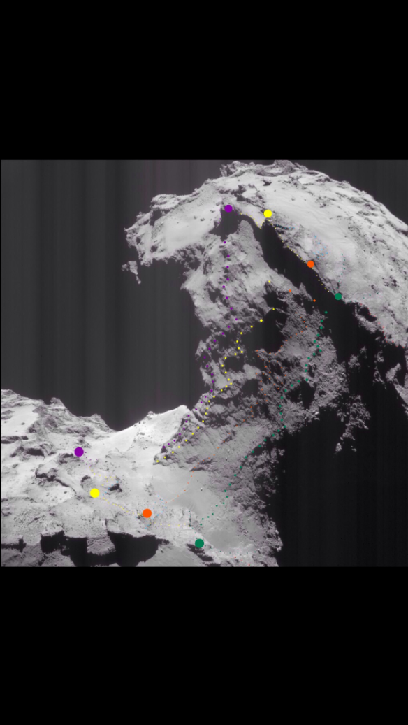
The four coloured lines are the classic four lines that each run all the way from their respective body matches to their respective head matches (larger dots). Incidentally, this is unequivocal proof of the neck stretching as the two lobes moved apart from being one single body. It’s been in the public domain since June 2015. The paleo equator ran between the yellow and orange dots when they were clamped together as two pairs between head and body. The orange line is therefore the southern delamination that’s closest to the paleo equator. However, it’s so close to the paleo line that it’s effectively on it. It’s been stretched both ways as the tensile forces of stretch plastered themselves against the back of the neck, trying to work out which was the best path to take, left or right. It follows a quasi-sin rule for a curved neck so the delamination forces only found their true direction some 100 meters or so to the north or south of the centre of the curve which is the centre of the neck and the paleo equator.
Confusion reigned in that 200-metre-wide strip, hence the squiggley, ripped-apart, 200-metre-wide orange line. It was pulled both ways and that ripping apart was more under the influence from the particular local shear resistances than the actual forces dividing, at the neck. The force-divide would happen neatly down the paleo equator line in an ideal world This is why the orange line has delaminated north and south (left and right) within itself as well as from the green and yellow lines. It’s wide and resembles puff pastry layers while its northerly and southerly neighbours are thin and well-defined. As we move north and south, the delaminations become more defined because the tensile forces, acting according to the sin rule had found their way round and were dragging the delaminations with greater and greater force. This is why the yellow and mauve lines splay out to the left.
It is of the utmost importance to stress that all these delaminations happened when the head was still attached to the body but herniating significantly. It was a proto-head with a bell-shaped rim at the shear line where it was about to shear. All the events described above, the plastering of the forces against the orange line, the forces not knowing which way to go and the sin rule all happened in concertinaed-together form around that bell-shaped rim at the shear line. After that, the head detached and the lines we see today are those compressed delaminations ticker-taped up the extruded neck. They went from compressed, delaminated lumps to long, slender, concertinaed-out lines. That’s why all four lines link their respective head dots to their respective body dots.
With this knowledge in mind, you can see that the mauve and yellow lines were sluggish about delaminating along the bell-shaped rim and so they were spread along the rim instead of a chunk sliding then ticker-taping upwards nice and vertically. Instead, the mauve and yellow lines were spread across from their original location to the ‘standard’ 100 metre or so displacement point instead of sliding (delaminating) in their entirety across that distance. This resulted in the spreading-across being like cards spread across a croupier’s table along the bell-shaped rim line. This therefore produced a diagonal ticker-taping and from halfway up only. The two lines are joined along their bottom half because the more buried part of the lump refused to delaminate. What appears to have happened is that yellow clung to mauve at the bottom of the lump while they both slid two ‘standard’ delamination widths i.e. 200 metres or nearly that.
The northward delamination process is the raison d’être for the C. Alexander gate: the two pillars, the mauve and yellow dots, are the topmost parts of the delaminated lumps that happened along the bell-shaped rim of the still-attached head. The lumps on the body are more commonly known on this blog as the four anchors (Part 24). They have qualities of being anchors, and did hold onto the head rim till the very last minute (Part 27). They also had more pliable material between them. But Part 24 was written before they were known to have delaminated from each other, with the head rim counterparts, before head shear. Even Part 25 struggles somewhat with the sideways movement and spread card analogy even though it got the ticker-taping between matching dots correct.
The northward delaminations continue northward, in stunted form, round the corner into the alcove between Anuket and Hathor. Here they stop because by now the northward component of the split tensile forces was running directly parallel to the Hapi rim, which is aligned with the long axis and therefore aligned with the tensile forces of stretch. It’s also why there’s such a sharp demarcation line between Anuket and Hathor in the alcove. And indeed, these longitudinal forces caused the Hapi rim which sheared along that line as well as the altogether different morphology of Hathor.
The green line in photo 7 is the first truly identifiable southerly delamination. It corresponds to the leftmost fuchsia line in photo 6 but is only fuchsia there because it’s southerly and so are the rest in photo 6. It should always be remembered as the green line because of its important relationship to the so-called green anchor which is the vestige of its compressed delamination (the larger green dot at the bottom). The other southern delaminations are in winter shadow (on the right of the neck) in photo 7 and were not known about until long after that photo was taken. Actually the second delamination is itself causing most of the shadow so you could say that’s visible and with three more in darkness.
THE TWO SPLIT TENSILE FORCE VECTORS SHAPED THE NECK
Finally, the upshot of the two long-axis tensile forces splitting to go round the back of the neck and down the north pole and south pole sides is that they shaped the neck to what it is today. It’s the reason for the cross-section of the neck being long and fairly narrow, with two evenly curved ends and long, straight sides. It’s also the reason for this elongation being almost in line with today’s rotation plane (equator) and exactly in line with the paleo equator.
Photo 8- the cross section of the neck from Hirabayashi et al. (2016). The link to the figure page is below it. Notice how the green spin axis arrow is at about 90° to the long axis of the elongated neck. Put another way, the red arrow of the comet’s long axis should be aligned with the long axis of the neck. It is but perhaps needs a small clockwise tweak. This is what the 12° correction back to the paleo long axis (and a consequent 12° for the spin axis too) would do. 
Nature 534, 352–355 (16 June 2016)doi:10.1038/nature17670/ Hirabayashi et al. (2016).
http://www.nature.com/nature/journal/v534/n7607/fig_tab/nature17670_SF2.html
ADDITIONAL PHOTOS
Photo 9- A view of Anuket/Hathor. Anuket with its northern delaminations is on the right but the green, orange and yellow delamination lines are whited out. The mauve one is in fact the zig zag edge just before we dip into the alcove. Then, in the alcove itself we see two more vertical lines that vaguely match the stronger mauve zig zag. They’re less pulled apart probably because they were buried and are stunted versions. 
Copyright ESA/Rosetta/NAVCAM – CC BY-SA IGO 3.0
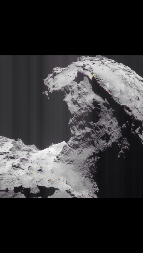
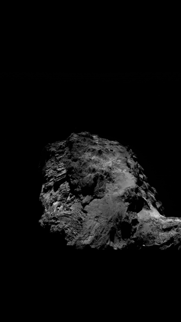
Photos 10 and 11- Two more views of Khonsu, unannotated for extra context. Notice how the second one shows up the ‘red’ tensile force vectors as being the same width as Apis and does so very clearly indeed. 
Copyright ESA/Rosetta/NAVCAM – CC BY-SA IGO 3.0

ESA/Rosetta/MPS for OSIRIS Team MPS/UPD/LAM/IAA/SSO/INTA/UPM/DASP/IDA/
Marco Parigi’s neck changes posts (the title of each one is in the second line of the link):
http://marcoparigi.blogspot.co.uk/2016/06/more-on-rockfall-area.html?m=0
http://marcoparigi.blogspot.co.uk/2016/09/anuket-crack-remodelling.html?m=0
http://marcoparigi.blogspot.co.uk/2016/08/animated-gifs-for-boulder-movement-in.html?m=1
http://marcoparigi.blogspot.co.uk/2016/06/lateral-movement-of-surface-in-anuket.html?m=0
PHOTO CREDITS
FOR NAVCAM:
Copyright ESA/Rosetta/NAVCAM – CC BY-SA IGO 3.0
To view a copy of this licence please visit:
http://creativecommons.org/licenses/by-sa/3.0/igo/
All dotted annotations by A. Cooper.
FOR OSIRIS:
Copyright: ESA/Rosetta/MPS for OSIRIS Team MPS/UPD/LAM/IAA/SSO/INTA/UPM/DASP/IDA/A.COOPER
