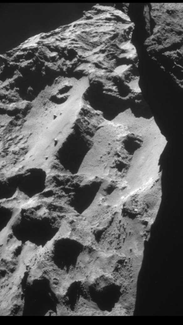
Are These The Dykes That Channeled Gases From The Core?
In Part 7 a working hypothesis for the first stage of the head shearing away from the body was presented. This included the proposition that a very deep, narrow chasm opened up between the head and the body as they initially separated, allowing internal heating, consequent large-scale sublimation and high-pressure outgassing at the shear line.
The next thing to look for would be evidence of gas/slurry conduits that might have formed spontaneously in that narrow crevice as it opened and found itself immediately pressurised with escaping gas. This would be streaming from the heated core where the incipient neck was just starting to stretch. These conduits might form spontaneously and be spaced fairly evenly apart in the same way that convection cells form spontaneously in almost even columns across a heat flux. They would radiate out from the centre to the rim in straight lines.
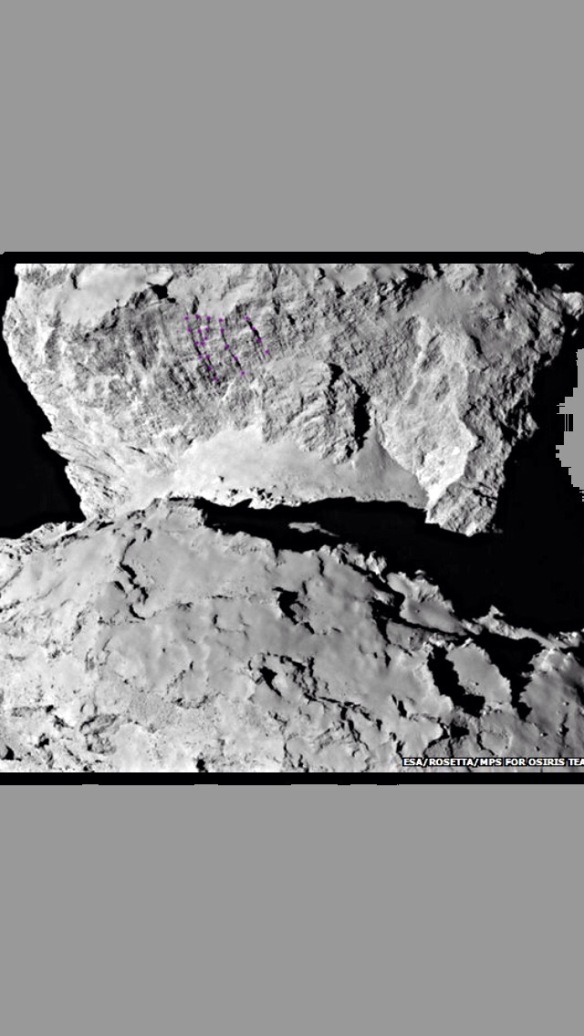
That is exactly what we see in the underside of the head lobe photos. These radial streaks going straight up the cliff have thus far been a complete mystery to everyone. Could they be the conduits?
The conduits shown in the header photo are just some of these radial lines. It just happens to be the only ESA photo that shows them fairly clearly as they exit at the rim but there are others streaming up all over the cliff. The original photo (zoomed out) and two other photos at the bottom of this post show the whole cliff with these few lines from the header photo denoted, again in mauve.
High-pressure conduits might well have been long and narrow, acting more like high-pressure kimberlite dykes than normal, low-pressure vents or fissures. This is because the initial gap between head and body would have been 500-700 metres deep and perhaps only centimetres wide. The gases would all have to flow one way, towards the shear line, while yet more heating and sublimation was pushing out gas relentlessly in their wake. The dykes would pressurise then force and scour their way out radially, come-what-may.
The lines we see do scour their way over and through the various lumps and bumps on the cliff and do so in very straight lines. They even straddle the large lump protruding from the bottom of the cliff. They also exhibit a number of apparent holes along their length which might be extra, sideways tributaries. What’s more, they run at right angles to any discernible strata so they can’t be strata lines.
Perhaps the best test to see if they were dykes is to see if these radial lines are trumpet-shaped at their outlets, like miniature versions of kimberlite pipes on the Earth. Real kimberlite pipes are long and thin and end in 1-2km long funnels which result from the explosive behaviour of the magma near the surface. This is similarly due to pressure drop.
It’s difficult to tell if the outlets are trumpet-shaped, looking at the NAVCAM photos, but there are several depicted in the header close-up that appear to be. These are around the rim of the cove on the head. Their accompanying dykes, if that is what they are, scour their way up the cliff, cutting through any protrusions on their way to their outlets. There are three outlets on the straight part of the cove rim, each with a small dot above them (which may be rocks or bleed-across outlets). The central outlet appears not to have its own dyke but may have been fed from the two either side. There is a fourth outlet just into the shadow of the step-up beyond the three rocks/outlets. And a fifth in the sunlight just beyond the step-up.
When seated on the body, the straight portion of the cove with the first four outlets would have been at the bottom rim of a straight-edged crater of the same width (see below). The emerging gases would have had no choice but to travel up from the crater floor as they emerged. The fifth outlet, beyond the step-up is actually emerging from a face that was formerly shunted against the body from the side (this small area being at roughly 90 degrees to the cliff). Its corresponding seating position on the body has what appears to be a gouged-out hole where the emerging gasses slammed straight into a wall before turning upwards and exiting. Three of the other four dyke outlets show some correlation with the scouring on the body although due to the very nature of scouring they aren’t perfect matches. To save boring readers with yet more head-body matches, the photos with the usual dotted annotations for the above matches have been relegated to the bottom of this post.
Regarding the three rocks or sub-outlets in the cove, the shadowing suggests two are rocks and one is a dip. However, they are fairly well aligned with the main outlets so one would deduce that they are all rocks or all sub-outlets. Whilst contemplating how to bring other evidence to bear on this, I realised that what I had seen as little strings of rocks impossibly aligned along the head lobe strata lines are probably very small dyke outlets. This would imply that all the stratum layers were under tension at one time (as we would expect in a spin-up or Roche pass at Jupiter) and were exhibiting the same behaviour as described above but with less gas, narrower dykes and no more than a minuscule amount of uplift. One of them, the weakest, had to give and that is the one we see yawning open before us.
HERE ARE THE MATCHES FOR THIS POST:
The photos are annotated with dots in the same manner as posts 1-7, with the key below them. The non-annotated versions are at the bottom of this post and are unzoomed for context.
Key:
Mauve: these show the dykes on the head lobe photo and their supposed pathway traced in ‘mid-air’ over the neck region on the body lobe. Material has since been eroded from this part of the body. Two of the body lobe tracks trace the path they would have if you could see them behind the head lobe (i.e. the two paths running into the black area).
Bright yellow: outlets from dykes that are discernible on the head lobe and their supposed position on the body.
Bright green: outlets that are less obvious on the head lobe one in shadow, the other supposedly fed by dykes on either side.
light blue: a matching ridge that used to step up from the crater on the body and from there the shear line curved round to the ‘gull wings’ discussed in Part 5. (This curving round is also matched when viewed from above in Part 4).
Dark green: the gull wings (see header photo, Part 5). The head lobe wings are fully visible but the body wings barely so. However, there are three dots depicting the very tip of one wing on the body. The end dot of the three corresponds to the top green dot on the head lobe photo. The slurry pile (one of two described in Part 7) is to be seen just below the wing tip on the body. The base perimeter is outlined with light yellow and each of three slumping tiers is dotted with terracotta. These tiers can be seen as being tightly constrained by the shape of the wing in the Part 5 header photo, suggesting it pushed up the wing some 20-40 metres.
Light yellow: see above.
Terracotta: see above.
Orange: a ridge set back from the cliff edge which curves round. This roughly matches features on the body that are set back from the course of the shear line which is the straight cut across the crater. Notice how the portion of the head cove (the true cliff rim) where the four adjacent outlets are, is very straight as well. This corresponds to the straight break across the crater.
Red: two diagonal, straight lines that seem to jump sideways from one dyke to another. Possibly bleed-across channels? They emerge near the corner of the crater where you might expect them to if seeking a path of least resistance. Whatever they are, they are quite well matched from head to body. On the body photo, only the ends are indicated to save cluttering with dots in that area.
Below are the original versions of all the photos in this post. Photo credits:
Copyright ESA/Rosetta/NAVCAM – CC BY-SA IGO 3.0
Header photo has additional processing by Stuart Atkinson at
This processed version was featured on NASA’s APOD site:
http://apod.nasa.gov/apod/ap141223.html
ESA Original

Two more cliff photos for context of where the dykes are. Zooming advised.


Hi Andrew. I think this is yet another angle that keeps this blog a couple of steps ahead of the mission scientists. Even as I had believed from the first sight of the duck shape that it had stretched, these radial lines had confused me until now. Demonstrating that they are probably dykes, and the forces and pressures that would cause them, connects a few more dots regarding the evolution of various related features. Of course, the forensic matching is of primary significance first to rule out previous formation theories; However, the easier process in explaining the dykes which do not have corresponding lines all the way, is still an important corollary. It is virtually impossible to explain the radial lines any other way, but quite consistent with known physics and thermodynamics with the stretch theory convincingly demonstrated if we just recreate the initial break mechanism.
LikeLike
Hi Andrew,
I have had trouble sending emails and so I just wanted to put a quick question here. Given Philae’s trajectory as from the following link:
I cannot see how it can reconcile with the proposed photogrammetric candidate solution we were looking at. Unless I am missing something?
LikeLike
Marco
I sent reply by email. If you also dont receive emails then let me know here and I’ll copy the email to here.
LikeLike